

Specifications
MagnaDrive ASD Model Selection
The MagnaDrive Adjustable Speed Drive (ASD) product line comes in four basic sizes: Small, Medium, Large and Mega. In order to identify generally which size is right for your application please review the Drive Sizing Chart below.
To select an ASD for your system, determine the maximum running horsepower and maximum running speed required by your pump or fan. The maximum speed and horsepower needed in a system with MagnaDrive speed control is usually less than in a fixed speed system using dampers or throttling valves. Both the speed and horsepower information is important, since the MagnaDrive ASD must be sized to deliver the maximum torque needed in your system.
The MagnaDrive ASD requires some slip between the driven speed and the output speed. The ASDs sized in this table have 1% to 4% slip when operated at full rated motor speed and torque. This information is for general sizing only. Contact MagnaDrive Application Engineering for detailed information on your particular installation.
MagnaDrive Adjustable Speed Drive Sizing Chart
Centrifugal applications only (pumps, fans, blowers, mixers). For non-centrifugal applications, contact MagnaDrive.
| Motor HP | Motor KW | 3600 RPM | 1800 RPM | 1200 RPM | 900 RPM |
| 10 | 7 | 6.5 | 6.5 | 8.5 | 10.5 |
| 15 | 11 | 6.5 | 8.5 | 10.5 | 12.5 |
| 20 | 15 | 6.5 | 8.5 | 10.5 | 12.5 |
| 25 | 18 | 8.5 | 10.5 | 12.5 | 12.5 |
| 30 | 22 | 8.5 | 10.5 | 12.5 | 14.5 |
| 40 | 30 | 8.5 | 12.5 | 12.5 | 14.5 |
| 50 | 37 | 8.5 | 12.5 | 14.5 | 16.5 |
| 60 | 45 | 10.5 | 12.5 | 14.5 | 16.5 |
| 75 | 56 | 10.5 | 14.5 | 16.5 | 18.5 |
| 100 | 74 | 12.5 | 14.5 | 18.5 | 20.5 |
| 125 | 93 | 12.5 | 16.5 | 18.5 | 22.5 |
| 150 | 112 | 14.5 | 18.5 | 20.5 | 24.5 |
| 200 | 149 | 14.5 | 18.5 | 22.5 | 26.5 |
| 250 | 186 | 16.5 | 20.5 | 24.5 | WC-1000 |
| 300 | 224 | 16.5 | 22.5 | 26.5 | WC-1000 |
| 350 | 261 | 18.5 | 24.5 | WC-1000 | WC-1000 |
| 400 | 298 | 18.5 | 24.5 | WC-1000 | WC-1000 |
| 450 | 335 | 20.5 | 26.5 | WC-1000 | WC-1000 |
| 500 | 373 | 20.5 | 26.5 | WC-1000 | WC-1000 |
| 700 | 522 | WC-1000 | WC-1000 | WC-2500 | |
| 750 | 559 | WC-1000 | WC-2500 | WC-2500 | |
| 1000 | 746 | WC-1000 | WC-2500 | WC-2500 | |
| 1500 | 1119 | WC-2500 | WC-2500 | WC-4000 | |
| 2000 | 1492 | WC-2500 | WC-4000 | WC-4000 | |
| 2500 | 1865 | WC-2500 | WC-4000 | WC-4000 | |
| 3000 | 2238 | WC-4000 | WC-4000 | ||
| 3500 | 2611 | WC-4000 | |||
| 4000 | 2984 | WC-4000 | |||
Installation and Dimensional Information
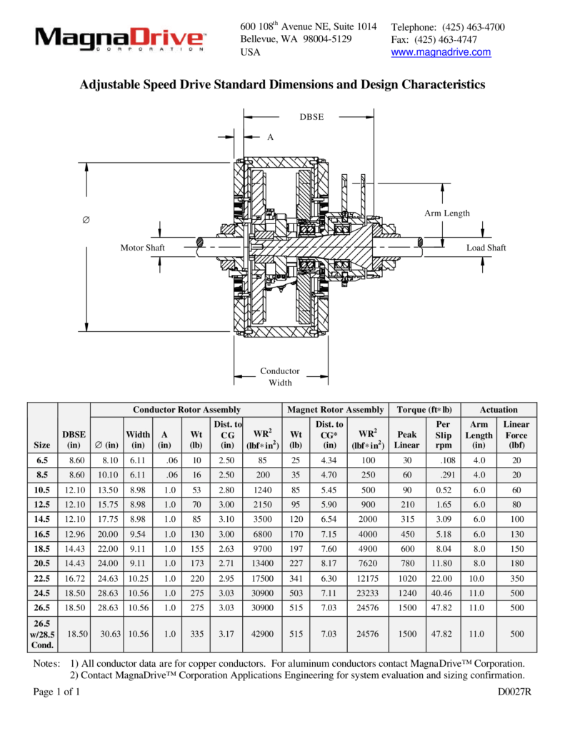
The ASD consists of two major components. The Copper Conductor Assembly is directly connected to the motor (input) shaft. Its weight is shown in the “Motor Shaft Weight” column of the table below. The Magnet Rotor Assembly and the Actuation Components are directly connected to the load (output) shaft, and their combined weight is shown in the “Load Shaft Weight” column of the table.
The overall dimensions required by the MagnaDrive ASD are defined in the cross-section drawing and the table. The axial distance needed between the end of the motor shaft and the end of the load shaft to install these two assemblies is stated in the “DBSE” column of the table. The actual diameters of your motor and load shafts will be used to size the mounting hub dimensions prior to the installation of the ASD.
The peak torque capacity is independent of speed, and is stated in the table.
Adjustable Speed Drive Standard Dimensions and Design Characteristics
MagnaDrive Actuator
The MagnaDrive ASD’s output is controlled by an actuator. The actuator allows the process control signal to modulate the speed or torque output of the drive to satisfy your process control requirements. MagnaDrive’s standard actuator is electric, although any form of actuator (hydraulic, pneumatic, etc.) can be utilized.
| Actuation Control Power: Control Signal Options: | 110 VAC 4-20 milliamp 1-5 vdc 0-10 vdc |
A manual control is also available by special order for systems where automatic process control is not appropriate.
MagnaDrive Motor Base and Installation Hardware
Adjustable motor mounting plates and actuator mounting hardware are available to facilitate installation. These items have been engineered to simplify the conversion and installation of the MagnaDrive system at the site. Contact us for details on these items.